2026-11-10 16:36:24
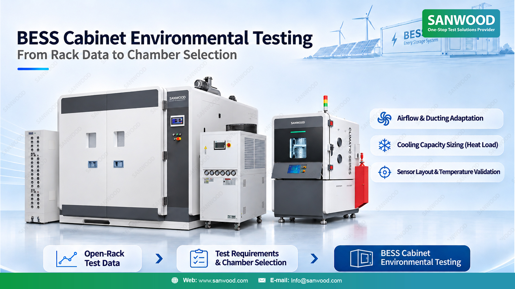
A battery rack can run warmer after it is installed in a battery energy storage system (BESS) cabinet, even when the environmental test chamber runs the same temperature program. The enclosure can change where the rack draws cooling air, how it rejects heat and which modules remain accessible for measurement. These changes matter when planning BESS cabinet environmental testing and selecting a walk-in battery test chamber.
Use open-rack data as a comparison baseline. Then define the cabinet-level measurements, heat-rejection path and loaded conditions needed for the assembled test. The aim is to establish which observations remain comparable, what the cabinet changes and which conditions the chamber must provide.
If the open-rack report includes upper and lower module surface temperatures, retain those measurement locations in the cabinet test where accessible. Use consistent sensor attachment methods and identify each channel on a measurement drawing. If a panel, bracket or cable route blocks an original location, document the replacement position. A relocated sensor measures a different position, so its reading should not be treated as a direct continuation of the original trace.
Before comparing runs, check the initial battery temperature and state of charge, the charge–discharge schedule and the cooling settings. Align temperature traces with identifiable events, such as the start of discharge. Record differences in the starting conditions or operating sequence that could affect the temperature response.
For an air-cooled rack, measure inlet air where it enters the rack. If the open-rack report has no equivalent reading, the new measurement describes the installed condition; it cannot establish how much the inlet temperature changed. That comparison requires readings from corresponding locations in both configurations.
Keep four quantities separately identified:
The chamber setpoint: the programmed temperature target.
Measured chamber air around the cabinet: the external condition at defined locations.
Rack inlet air: the cooling air reaching the rack.
Module surface temperature: the battery assembly’s response at the selected measurement point.
Surface measurements describe the instrumented locations. They do not establish the temperature of every module or the internal temperature of each cell.
Suppose the upper module runs warmer after installation, rack inlet air is also warmer, and measured air around the cabinet remains comparable. This pattern gives the team a reason to investigate the cabinet’s internal air path, including whether warm exhaust reaches the inlet. It does not, by itself, establish the cause.
The assembled cabinet should be described as carefully as the temperature program. Record the installed panels, door position, rack arrangement and cooling configuration. If a door remains open to accommodate instrumentation, the resulting airflow may differ from the closed-cabinet condition the test is intended to assess.
Plan measurement access before loading the cabinet. Identify how sensor wires reach the required locations and whether their routing affects panel closure or obstructs an inlet. Where access openings are necessary, document their condition during the run so that later comparisons use the same setup.
The chamber's airflow also needs attention. Cabinet orientation and clearance determine how its inlets and exhausts interact with the chamber supply and return air. Direct exposure to a supply outlet may create a different local condition from another position in the workspace. Show these relationships on the layout rather than relying only on the chamber’s nominal internal volume.
For SANWOOD, a cabinet drawing and sensor map provide practical inputs for reviewing the chamber air-distribution arrangement. They also help distinguish chamber-control sensors from independent measurements used to observe the cabinet and rack.
An idle cabinet and one charging or discharging during the same climatic profile can place different demands on a battery test chamber. Document the operating stages that release heat, when they occur and how long they last. Identify other equipment inside the workspace that contributes heat during the test.
Pay particular attention to operating stages that overlap with a downward temperature transition. Under those conditions, the refrigeration system may need to remove operating heat while also cooling the cabinet, batteries and fixtures. A capacity assessment should therefore consider the planned load at the required temperatures and transitions.
For a liquid-cooled cabinet, trace where the cooling system ultimately rejects heat. An external cooling loop may carry part of the heat outside the workspace, while cabinet components and exposed surfaces still exchange heat with the chamber air. If the cooling system releases its heat inside the workspace, that contribution belongs in the chamber heat-load assessment.
Provide estimated heat release in kW where available, with the relevant operating stage and the basis of the estimate. Distinguish heat entering the chamber air from heat carried outside by the cooling circuit, and avoid counting the same contribution twice.
The cabinet's rated energy capacity in kWh does not, by itself, determine the heat load the chamber must remove. Where heat-load data are incomplete, identify the missing values and assumptions before agreeing on loaded temperature performance.
The useful specification connects each cabinet requirement to a chamber design decision.
| Information to provide | What it helps determine |
| Cabinet orientation, inlet and exhaust locations, and panel configuration | Clearance and the relationship between cabinet airflow and chamber supply and return air |
| Heat released into the workspace during each operating stage | Refrigeration capacity under the planned load and temperature profile |
| Cabinet, battery and fixture mass, with required temperature transitions | The thermal load that must be considered alongside operating heat |
| Sensor map, cable routes and connection locations | Measurement access, chamber-control sensor placement and test-lead routing |
| Loaded dimensions, weight and handling method | Usable workspace, door opening, floor loading and installation access |
The SANWOOD Walk-In Battery Pack Test Chamber provides a starting point for this assessment. SANWOOD can adjust air duct layout, refrigeration capacity and sensor placement according to chamber volume, battery heat load and test requirements.
For a cabinet with a side-facing inlet, for example, its orientation and available clearance should be considered alongside the proposed chamber air-distribution layout. The resulting configuration should address both the space occupied by the cabinet and the environmental conditions required around it. For detailed loading and access considerations, see the EV and ESS battery chamber sizing guide.
Before finalizing the specification, agree on the installed configuration and operating state used for the chamber performance check. Define the temperature measurement locations, permitted deviations and the condition that starts any dwell period. If verification uses an empty chamber or a representative load, identify what that arrangement demonstrates and which conditions remain to be assessed for the assembled cabinet.
Keep chamber performance requirements separate from cabinet acceptance criteria, such as module temperature limits. This preserves a clear distinction between the environment supplied by the equipment and the battery system’s measured response.
A BESS cabinet project brings together mechanical access, air distribution, refrigeration and instrumentation. These requirements need to remain consistent as the proposal moves into manufacturing and equipment verification.
SANWOOD's manufacturing facility spans more than 30,000 m², with teams covering structural design, refrigeration, assembly, quality control and pre-testing. These disciplines are relevant when translating cabinet dimensions, operating heat and measurement needs into a chamber configuration.
A separate battery temperature test chamber delivery report describes a project progressing through manufacturing and factory inspection to on-site commissioning and handover. It provides background on SANWOOD's equipment delivery experience; the performance requirements for a BESS cabinet installation still need to be defined for that project.
Open-rack data provide a baseline for selecting measurements and interpreting changes. If the test objective depends on airflow, cooling or module temperatures inside the installed cabinet, measurements on the assembled cabinet are needed under the relevant operating conditions. Retain useful rack-level data and identify which observations require confirmation after assembly.
For a test intended to represent the assembled cabinet, use the door, panel and cooling configuration defined in the test plan. Record any openings needed for instrumentation because they may change airflow. An open-door diagnostic run can help investigate a temperature pattern, but its results describe that altered configuration.
An external cycler may be considered as part of the proposed test arrangement. Share its location, cable sizes, connector dimensions and cabinet connection points so that chamber ports and routing can be assessed. The setup also needs defined electrical measurement responsibilities and any required alarm or shutdown interfaces; cable access alone does not establish compatibility.
To discuss a BESS cabinet project, contact SANWOOD with your cabinet layout and planned environmental and operating profiles. Include available rack temperature records, sensor locations, cooling details and heat-load estimates. Identify missing information so the initial discussion can establish the next engineering steps and the conditions the proposed chamber must support.
Sanwood is not just a company; it is a commitment to delivering high-quality products that stand the test of time.

 English
 中 文


 info@sanwood.com